Announcement

Collapse
No announcement yet.

This is a huge longshot but I'll give it ago

Collapse
X
 
  • Filter
  • Time
  • Show
Clear All
new posts

    This is a huge longshot but I'll give it ago

    Has anyone fitted a Durite 0-743-12 relay ? It keeps the lights on for ten seconds after closing the door.

    I'll leave it there at this stage due to the fact that it's so particular.

    Cheers


    #2
    Originally posted by Stimpy View Post
    Has anyone fitted a Durite 0-743-12 relay ? It keeps the lights on for ten seconds after closing the door.

    I'll leave it there at this stage due to the fact that it's so particular.

    Cheers


    Amazon have http://www.amazon.co.uk/Durite-Relay.../dp/B0085S5P4U

    And here http://www.ebay.co.uk/itm/Durite-Rel...21194020655%26


    Getting cheaper http://www.hallselectrical.co.uk/rev.../list/id/5816/

    There are plenty out there

    Ian
    Last edited by milothedog; 20 March 2013, 08:25.
    Wise men ignore the advice of fools, but fools ignore the advice of wise men sigpic

    Comment


      #3
      My cat 2 alarm has interior light delay - I initially classed it as a gimmick in a Stag, but it's a lot more useful than I thought it would be...
      Last edited by GDPR; 20 March 2013, 08:44.

      Comment


        #4
        Hi
        Durite products are good quality so not a problem there, the only concerns I have is that generally Durite do not supply wiring diagrams for their products, and therefore you would be on your own. This is a new product to me having been out of the auto electrical trade for some time now, while it sounds quite a simple thing to fit after all it is only a delay relay, fitting it could prove to be more complex than first thought. The relay obviously would need to go into the feed from the door switches, and not the interior light control switch. The relay has four terminals so obviously it will probably requires additional wiring (power and return probably), so depending what car you plan on fitting it to how much of a problem is this? But good luck if you do go ahead.

        Ken

        Comment


          #5
          Originally posted by Motorcycle mad View Post
          Hi
          Durite products are good quality so not a problem there, the only concerns I have is that generally Durite do not supply wiring diagrams for their products, and therefore you would be on your own. This is a new product to me having been out of the auto electrical trade for some time now, while it sounds quite a simple thing to fit after all it is only a delay relay, fitting it could prove to be more complex than first thought. The relay obviously would need to go into the feed from the door switches, and not the interior light control switch. The relay has four terminals so obviously it will probably requires additional wiring (power and return probably), so depending what car you plan on fitting it to how much of a problem is this? But good luck if you do go ahead.

          Ken

          Aren't relay's 4 or 5 pin normally. 2 for the coil 85 & 86 and 2 for the contacts 30 & 87 and 87a on a 5 pin

          Ian


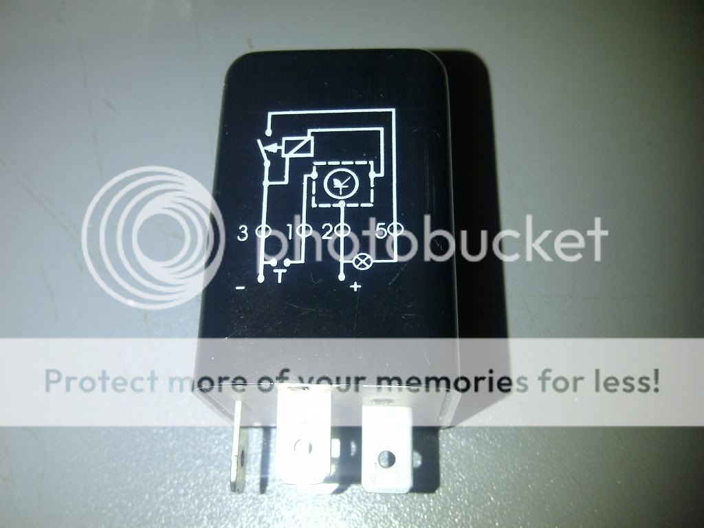
          This may help, (1 = door switch, 2 = + feed, 3 = - earth, 5 = - side of lamp) from one of the web sites
          Last edited by milothedog; 20 March 2013, 09:21.
          Wise men ignore the advice of fools, but fools ignore the advice of wise men sigpic

          Comment


            #6
            Originally posted by milothedog View Post
            Aren't relay's 4 or 5 pin normally. 2 for the coil 85 & 86 and 2 for the contacts 30 & 87 and 87a on a 5 pin

            Ian


            This may help, (1 = door switch, 2 = + feed, 3 = - earth, 5 = - side of lamp) from one of the web sites
            Hi Ian
            You are correct in as far as a normal relay is concerned i.e. a 4 pin relay is simply an on/off electrical operated switch, while a 5 pin is normally a changeover relay, like a dip switch, but this is not a standard relay. When I made my original response I had not looked at the other web sites you had made reference to, but now having done so, the Green Spark site giving the terminal numbers and connections making it look simple, so I will wait for someone to fit one.

            Ken

            Comment


              #7
              Originally posted by Motorcycle mad View Post
              Hi Ian
              You are correct in as far as a normal relay is concerned i.e. a 4 pin relay is simply an on/off electrical operated switch, while a 5 pin is normally a changeover relay, like a dip switch, but this is not a standard relay. When I made my original response I had not looked at the other web sites you had made reference to, but now having done so, the Green Spark site giving the terminal numbers and connections making it look simple, so I will wait for someone to fit one.

              Ken


              Ian
              Wise men ignore the advice of fools, but fools ignore the advice of wise men sigpic

              Comment


                #8
                My wanting of a 10 sec delay is for reasons other than looking 'cool' -)
                I want it so when you get into your car get all in order before being ready to drive (I'm putting a tiny blue lamp that shows the ign key)
                Also - how about this... I'm doing the same thing on the hand break so that the seatbelt sign shows until you release the handbrake and then it stays for 10 secs.

                I'll reply to the rest later - I'm going back into the bloody car with a bedside light and a heater!

                Comment


                  #9
                  Ok - there was another 5 hours of time with no result (plus yesterday and the yesterday before ..etc..).

                  First and foremost - A big thank you for all your suggestions - even though my set up is somewhat unique

                  This is how the story goes:-

                  The electrics on the dash area were rubbish and no indoor courtesy light worked

                  So I :-

                  1 - Resolved electric issues
                  2 - brought out all the leads (ie not diconnect them as such)
                  3 - First stop - the T-bar lamp. I posted on another thread that I basically rewired it by sending up two wires - one for +ve and 1 for earth (I realise how the earth controls lighting now - it's a case of doing something that 'offers' earth to then light a bulb or whatever. Anyway - the light went on. The switch on the central console worked nicely (I only had 2 wires connected using 'my' method. The door also illuminated my light. Hooray!
                  4 - then I thought about some nice improvements these were-

                  10 sec delay on closing the door (T-bar + each side of console)
                  10 sec delay on releasing handbrake (wired to the seatbelt warning light)
                  Buzzer if you opened the door with ign off and lights on.

                  It all went beautifully (many hours were used to get to this point so /I was a little bit proud of myself !!)
                  I recarpeted - hiding cables and all that,

                  Then - badness.

                  The lights-on warning buzzer did not work - and I was damned if I didn't fix it.
                  So -from a beautiful finish I tore up the carpet and checked things.

                  I spent many hours trying to resolve.

                  IT was getting silly - so I just un-connected / released choc blocks etc etc

                  So now I have a Stag with a tatty intrerior with an owner in (almost) tears.

                  So - I did a bit of basic checking - eg wired up one of the footwell lights straight to +ve and earth - all working. Ok so far so good.

                  Then I reintroduced the relays. These worked beautifully before - like - spot on. Also, before, I found them a joy to fit - wired up and worked first time.
                  But now nothing. Hours and hours - changing wiring and experimenting on the way but to no avail.

                  I beg you all - WHAT have I done!! <hand pounding the table>

                  To milothedog, I'm really indebted to your attempts - obviously searching the web to help me - I so much thank you.
                  You mentioned:

                  This may help, (1 = door switch, 2 = + feed, 3 = - earth, 5 = - side of lamp)

                  Ok - to those with a superior knowledge to me (i.e. all the above) his is exactly what I did:

                  (please realise that I did some basic tests on the way)

                  Cable ONE:
                  cabled up a wire from male 1 straight to the door switch (that turns the puddle lamp on and off). I realise that opening the door 'mates up' the spring button.

                  Cable TWO:
                  wired this to a permanent live cable

                  Cable THREE
                  wired this to an earth point

                  Cable FOUR
                  Does not exist

                  Cable FIVE
                  Connected this to the -ve of the lamp - and tried it on the +ve of the lamp.
                  This bit confuses me - as you correctly say "5 = side of lamp" does that mean something other to how I read it? ie connect to the bulb.

                  I remembered last time I did the install I heard reassuring clicks from the relay - but not this time.
                  I have two of these relays and both behave the same so I'm not too keen on thinking the relay is broken.

                  The relay decription looks obvious -

                  To get the bulb to light you need (on the relay) a switch to turn it on/off, as with many things it needs an earth, it needs current in order to do anything and finally a cable coming out of the relay to manage the bulb.

                  So what the %%%% is going wrong?? Is there something I'm missing out onor doing wrong? Especially the ambiguous 'side of lamp' instruction - like what is the 'side of lamp''? From that description (which is numerous across the web) you simply lay some cabe to the side of the lamp (obiously I didn't do that)

                  If anyone can help me they will be a cyber-friend fir life (or is that a turn off?!?!)

                  Comment


                    #10
                    Some individual responses to some:

                    To motorcyclemad - there were instructions - which I lost (!!!) (kicking myself in the face, which is hard to do) bit numerous sites show a consistent pattern.

                    Milothedog - I'll check those links - but I'm pretty sure the unit Im talking about is ok as i have 2,

                    Incidentally - emailing duralite seems to be ignored - which is a shane

                    ...but thanks to everyone who got involved!

                    What is that ambiguous bloody thing about "side of light;?!?!Jeez

                    Comment


                      #11
                      Is this what you have! looks to me as if pins 3 & 1 are switched by the door and 2 & 5 control the lamp via the timer. so you need a live feed to pin 2 , a neg on pin 3 and through the door switch for pin 1 to a neg. and pin 5 to the other side of the lamp. I think you need to look at how the door switches are wired on your car firstly (there are 2 different types I think)as that's where the problem may be with trying to integrate this in to the circuit. Ian

                      Last edited by milothedog; 21 March 2013, 09:16.
                      Wise men ignore the advice of fools, but fools ignore the advice of wise men sigpic

                      Comment


                        #12
                        You have made a 'logic' approach - which is v helpful.
                        Bear in mind I already had this set up running before - that's what makes it more miserable (I have 2 units)
                        And what do they mean 'the side of the lamp' as iin the original instrctions? Does it mean -ve lead of the bulb

                        Thanks again

                        I love this forum!

                        Comment


                          #13
                          Originally posted by Stimpy View Post
                          You have made a 'logic' approach - which is v helpful.
                          Bear in mind I already had this set up running before - that's what makes it more miserable (I have 2 units)
                          And what do they mean 'the side of the lamp' as iin the original instrctions? Does it mean -ve lead of the bulb

                          Thanks again

                          I love this forum!

                          That's how I read it from the picture, the lamp is getting a pos from the shared connection on pin 2 and when the contacts are closed it gets it's neg from pin 5 are there any other better electrical brains that can help

                          Ian.

                          Just a thought, why not rig up a simple circuit on the bench to prove your relays are OK


                          Another thought is what are you testing the circuits with. Don't use a test lamp as the current it draws, in some cases, (Lamp wattage) will fry electronic components (timer in the relay maybe) use a DMM (digital multimeter).
                          Last edited by milothedog; 21 March 2013, 16:59.
                          Wise men ignore the advice of fools, but fools ignore the advice of wise men sigpic

                          Comment


                            #14
                            Well Eureka! I have won the battle!

                            I disregarded the instructions and then - literally - played with cables.

                            I found a combination which audibly caused a switch clunk. I tried to map it up with the lamp but it stayed on. Literally - swapping things over caused the lamp to work as directed. My "HOORAY" could be heard in Swansea.

                            I mapped the other relay accordingly and it worked too.

                            So - in appreciation to the efforts of all can I make a suggestion for a great utility for stag owners where the stag can't communicate with the dash seatbelt sign. By wiring it (10 sec relay) up using the hand brake + light in a certain way) - you can start the car and the seatbelt light comes on and stays on. As you release the parking brake it stays lit for 10 secs. Nice one!

                            Thanx again to all!!!!!

                            Comment

                            canli bahis siteleri bahis siteleri ecebet.net
                            Chad fucks Amara Romanis ass on his top ?????????????? ???? ?????? ?????? ? ??????? fotos de hombres mostrando el pene
                            güvenilir bahis siteleri
                            Working...
                            X