Announcement

Collapse
No announcement yet.

Plumbing Diagram / photo for a Mk1 stagweber header tank

Collapse
X
 
  • Filter
  • Time
  • Show
Clear All
new posts

    Plumbing Diagram / photo for a Mk1 stagweber header tank

    I have just got my Stagweber header tank and thought the instructions that come with it would be better than they are.

    It starts by stating its based on a Mk2 but also throws the odd remark about the Mk1... but thats about it. It does not say where in length to cut pipes, the best way to layout things, no plumbing diagram or photos or well anything. Still I am sure once I know what its meant to be it will be easy.

    So has anybody got either or both a plumbing diagram or photographs of how it should look on a Mk1. Their youtube video only shows a mk2.

    Any help, tips, advice etc would be most welcome. Maybe I am ovethinking it and its just the same, but I am left with many questions at the moment.

    Dave
    #2
    I can't remember the differences between the two so sorry I can't advise, but have you tried contacting Stagweber for instructions for fitting to the Mk1?? You can't be the first customer who wants to fit one to a MK1 system. It makes sense to me to ask the supplier first before throwing the question out to a wider audience.

    Roger
    Now Stagless but have numerous car projects
    So many cars, so little time!

    Comment


      #3
      The large outlet from a header tank has to go into the low pressure side (bottom hose) the bleed or feed small inlet to the tank has to come from the high pressure side (top hose) . Other configurations are pretty pointless, but have been proudly displayed!!!!! I’ll get me hat & coat now....(don’t have a header tank, have got a few hats)
      There are 2 secrets to staying on top :- 1. Don't give everything away.
      2.

      Comment


        #4
        Hi Dave, I can take some photos for you as I have it fitted to a Mk1. I would add though that I have just blanked off the float switch as it has been leaking and is a little troublesome. I did try to find a more robust (metal) switch but so far have not identified one.

        Regards
        Brian

        Comment


          #5
          A few for starters. Sorry its dark out there and had to use a light. If there's anything in particular you want to know please ask.

          You do not have permission to view this gallery.
          This gallery has 3 photos.

          Comment


            #6
            Thanks for helping Brian. Your radiator apears to be that of a Mk2, i.e. I have a pressure cap on the radiator, and its this part that particuarly confusing to me.

            The stagweber kit includes a new pressure cap.. which you need for the tank, except he has included a 20flb cap.. when the original is only 13.. which leads to all sorts of questions such as the ones below which I have sent to Stagweber:
            1. The Mk1 is pressurised to 13flb. The new cap supplied is 20flb which for the Mk2 is correct. Will it damage my Mk1 system fitting the 20flb cap?
            2. As I have a cap on the radiator and a cap for the new expansion bottle where do I put each cap?
            3. If there is a 13flb and a 20flb cap, whats the point of the 20flb cap as the 13flb cap will always blow first?
            4. Is the tiny pipe at the cap on the new expansion tank mean to to to the old mk1 expansion bottle?
            5. Where does the expansion pipe that is currently just below the radiator cap on the radiator now go?
            6. If the radiator now overheats where will the excess coolant go?
            More than all this, from what I can understand, on a mk1 as in its original format, people said if it overheated then the excess fluid would go to the expansion bottle(true) but it could not return due to it being so low down. To my view point it not returning was not in the main due to it being low, more that the radiator cap acts like a 1 way valve.. letting fluid past when pressure is high, but then re-closing and never re-opening ever to let fluid come back in... admittedly it could not come back due to the bottle being low BUT a valve is a valve and it would never open to let it do so anyway. On the Mk2 they fixed the valve / cap part, but not the height of the bottle.

            By the way, and I am sure I am not the only one, I intend to connect the float to the Temp indicator on the cluster that is only founf on the mk1 - very kind of Triumph to think of our future use.

            Dave
            Last edited by Bakdraft007; 5 January 2020, 19:48.

            Comment


              #7
              Originally posted by Bakdraft007 View Post
              More than all this, from what I can understand, on a mk1 as in its original format, people said if it overheated then the excess fluid would go to the expansion bottle(true) but it could not return due to it being so low down. To my view point it not returning was not in the main due to it being low, more that the radiator cap acts like a 1 way valve.. letting fluid past when pressure is high, but then re-closing and never re-opening ever to let fluid come back in... admittedly it could not come back due to the bottle being low BUT a valve is a valve and it would never open to let it do so anyway. On the Mk2 they fixed the valve / cap part, but not the height of the bottle.


              Dave
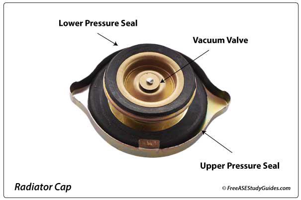
              The radiator cap will allow the coolant to be drawn back into the radiator when it cools down, there is a second "vacuum" valve which opens and allows the expanded coolant to be drawn back into the radiator. The height of the expansion tank is irrelevant in that system design.

              This site gives a nice clear explanation of the workings of a radiator cap.

              What does a radiator cap do? The radiator cap maintains a constant cooling system pressure while allowing coolant to flow back and forth to the overflow or resevoir tank. As coolant heats it contracts. The cap acts as a two way valve the allows coolant to flow to and from the overflow.


              Roger

              Now Stagless but have numerous car projects
              So many cars, so little time!

              Comment


                #8
                Hi Dave

                First point of contact would be StagWeber for instructions on how they recommend that it be installed.

                But beware please

                I have a Thomas (the tank engine) header tank like MLCstag and experienced that the plumbing (suggested when I purchased) could* allow coolant to bypass the radiator.

                The instruction was/IS to cut and fit a t-piece into the middle of the heater U pipe hose on top of the water pump inlet. The return pipe was to radiator inlet (fat hose to the top of the radiator) or to a right angle on the mk2 filler plug.

                I was able to prove that my hot running issues were because of this setup because once I blanked it off the return/air bleed, my cooling hot running issues were resolved. I can only assume that under certain circumstances the water pump could draw coolant direct from the header tank (as it was the source of least resistance) run it around the engine and send it back to the radiator, but because of the vacuum in the header tank it doesn't quite get there.

                Interested to see if StagWeber are still recommending the T-piece into the heater inlet hose like they are in the 2015 video on youtube
                Stags and Range Rover Classics - I must be a loony

                Comment


                  #9
                  Originally posted by marshman View Post

                  The radiator cap will allow the coolant to be drawn back into the radiator when it cools down, there is a second "vacuum" valve which opens and allows the expanded coolant to be drawn back into the radiator. The height of the expansion tank is irrelevant in that system design.

                  This site gives a nice clear explanation of the workings of a radiator cap.

                  What does a radiator cap do? The radiator cap maintains a constant cooling system pressure while allowing coolant to flow back and forth to the overflow or resevoir tank. As coolant heats it contracts. The cap acts as a two way valve the allows coolant to flow to and from the overflow.


                  Roger
                  Thanks for that Roger... all these years and I never new that! Very interesting. As you say, it would not seem that the height of the bottle matters... so again, it sort of blows the theory that the bottle being mounted low caused a problem in the first place?

                  It also creates a further mystery about how the stag webber tank is meant to work. It seems I should really have the 20lb cap on the radiator and the 13lb cap on the tank, with the thought that the 20 cap on top of the radiator will not open before the one on the tank and the system will be 13lb limited. However if 20lb is OK to use on my mk1 and will not damage it then maybe 13 on the radiator (the spigot being bunged) 20 on the tank, so the system would be limited to 20.

                  The instructions do not mention what the overflow spigot on the new tank is connected to. They say the original overflow tank is redundant, but then it makes more sense to connect it to the original bottle as it would act in the same way as the original and why waste the coolant if it overheated... I may need it when it cools back down!

                  Its funny really, the instructions made no sense to me at first, but the more I read them, the more they make sense, especially with your help to explain how things work.

                  I will wait to see what Chris at Stagwebber says.

                  Comment


                    #10
                    So tempted to comment, but..............

                    Dave
                    1974 Mk2, ZF Auto, 3.45 Diff, Datsun Driveshafts. Stag owner/maintainer since 1989.

                    Comment


                      #11
                      Originally posted by richardthestag View Post
                      Hi Dave

                      First point of contact would be StagWeber for instructions on how they recommend that it be installed.

                      But beware please

                      I have a Thomas (the tank engine) header tank like MLCstag and experienced that the plumbing (suggested when I purchased) could* allow coolant to bypass the radiator.

                      The instruction was/IS to cut and fit a t-piece into the middle of the heater U pipe hose on top of the water pump inlet. The return pipe was to radiator inlet (fat hose to the top of the radiator) or to a right angle on the mk2 filler plug.

                      I was able to prove that my hot running issues were because of this setup because once I blanked it off the return/air bleed, my cooling hot running issues were resolved. I can only assume that under certain circumstances the water pump could draw coolant direct from the header tank (as it was the source of least resistance) run it around the engine and send it back to the radiator, but because of the vacuum in the header tank it doesn't quite get there.

                      Interested to see if StagWeber are still recommending the T-piece into the heater inlet hose like they are in the 2015 video on youtube
                      Very interesting... yes... they still are reccomending the T-piece into the heater inlet as described. I can see exactly what you are saying and can see why it would happen as you describe. You would wonder wether it would be better to connect it there with an unequal T piece. with the smaller part of the T going to the tank. This way you create a path of higher resistance to the tank. After all the only reason for the connection is to primarily keep the system topped up with a place for air to go? Did you try that?

                      Dave

                      Comment


                        #12
                        Originally posted by DJT View Post
                        So tempted to comment, but..............
                        Awww... go on... I know you must have been round the houses a million times on this subject... but I am a newbie and keen to learn from the master...

                        Comment


                          #13
                          Originally posted by Bakdraft007 View Post

                          Awww... go on... I know you must have been round the houses a million times on this subject... but I am a newbie and keen to learn from the master...
                          There is plenty on this subject in this Forum. Use the search facility and settle down for a long read..........
                          Dave
                          1974 Mk2, ZF Auto, 3.45 Diff, Datsun Driveshafts. Stag owner/maintainer since 1989.

                          Comment


                            #14
                            in my experience and from looking at other factory header tank installations (Such as my 1993 Range Rover) the header tank gravity feeds into the radiator bottom hose and returns back to the top off the radiator. To ease this the header tank is more often than not found on the radiator outlet side.

                            Alas that area on a Stag is a bit busy with PAS pump, battery, washer bottle and brake master. Thus I have converted my HT into a high level expansion tank, the air bleed hose back to the top of the rad is blocked off, this gives me a head of water above the top of the radiator and a handy gravity feed to assist the refilling of the rad when cooling down. I fitted a TR7 low fuel level warning stabiliser to control the constantly flickering low water light.

                            How do EJ Wards recommend their HT installation is plumbed in?
                            Stags and Range Rover Classics - I must be a loony

                            Comment


                              #15
                              Originally posted by richardthestag View Post
                              in my experience and from looking at other factory header tank installations (Such as my 1993 Range Rover) the header tank gravity feeds into the radiator bottom hose and returns back to the top off the radiator.
                              Many years ago I fitted a Volvo HT (followed by many others since) which is fitted with a low level alarm switch. Intuition guided me to a similar installation to that described in your first paragraph, which was confirmed when I spoke to a respected Stag expert formerly of this Forum. I had a 15mm boss fitted low down on the LH side of the radiator and a 8mm boss fitted to the filler plug tube. This gives gravity feed and air vent return. The original expansion tank ford pipe across the top of the radiator is blanked off. Since this was fitted, I have covered some 45,000 miles without problem. Even Mr StagWeber himself complimented me on the simplicity of the installation when he saw it at Beaulieu National Day last year.
                              Both header tank and switch were replaced with brand new items from PFS Parts last year for a total of less than £50 as the original ones I fitted were salvaged from a 1996 Volvo in a scrapyard about 14 years ago.

                              448E7264-2D71-4441-B21E-F424FFB885F3.jpeg
                              Last edited by DJT; 6 January 2020, 14:16.
                              Dave
                              1974 Mk2, ZF Auto, 3.45 Diff, Datsun Driveshafts. Stag owner/maintainer since 1989.

                              Comment

                              canli bahis siteleri bahis siteleri ecebet.net
                              Chad fucks Amara Romanis ass on his top ?????????????? ???? ?????? ?????? ? ??????? fotos de hombres mostrando el pene
                              güvenilir bahis siteleri
                              Working...
                              X